Home Assistant ESPHome Window/Door Monitor
When building a new home, there are a lot of home automation provisioning to be done while the walls are open. My goal is to hard-wire as much as possible. WiFi is great, but it's never going to be as reliable as a copper connection. Additionally, with ethernet, you can provide power via POE to your end devices. This reduces the number of power points you need to provision into areas where you wouldn't usually provision power.
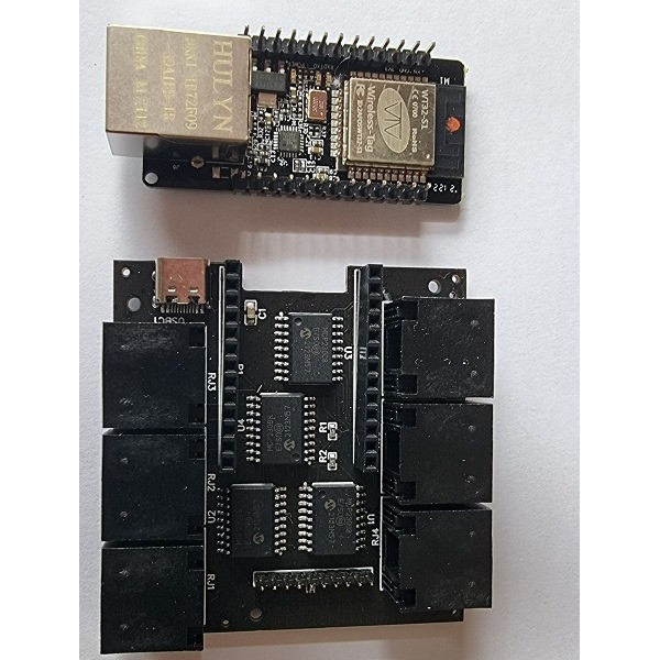
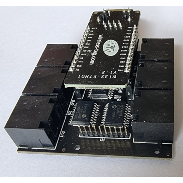
The new house has WT32-ETH01 from Wireless-tag is a compact ESP32, with an integrated LAN7820 ethernet port onboard. They lack POE, but I already have several POE adapters that I can utilize for this function.
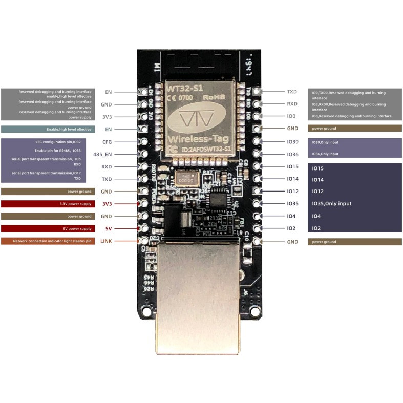
The WT32-ETH01 has 10 usable GPIO pins after the LAN7820 has been added. 3 of these ,35,36,39 are input only and do not have internally programmable pull-up resistors. (more on that later).
Adding GPIO's
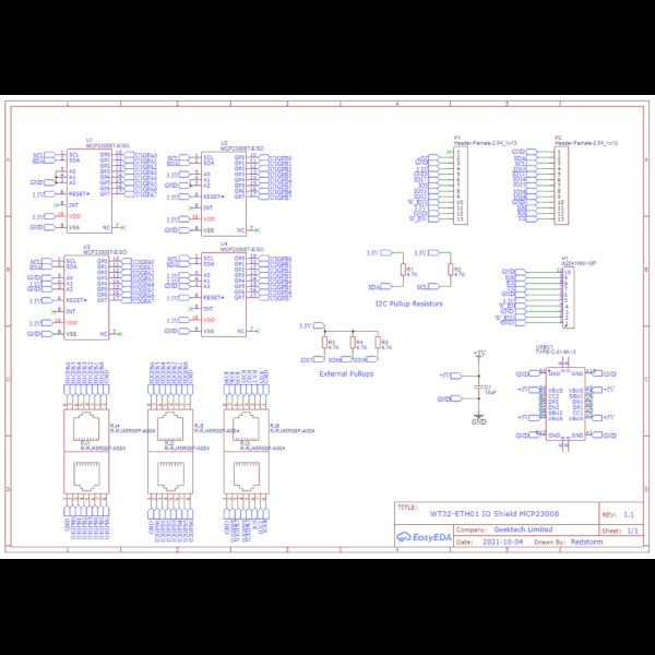
To provide the required number of GPIO pins to monitor all the doors and windows, I used 4 x MCP23008 IC. Each one provides 8 GPIO's via an I2C interface and up to 8 can be addressed on the bus. I initially designed the circuit using MCP23017 IC's that provide 16 GPIO's each however, due to global chip shortage, the factory did not have stock of this part. So I reverted to plan B, which is slightly more expensive, due to 4 IC's being required. (4 x $2.20 vs 2 x $3.12)

Note: If you use the MCP23016 these do not have internally programmable pull-up resistors. The MCP23008 and MCP23017 both have internally programmable pull-up resistors which suit my project, because they are used as a binary sensor.
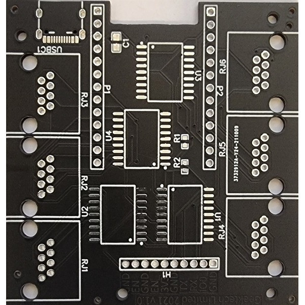
Circuit Design
Online Circuit Design and Manufacturing by EasyEDA. Using the online browser-based design tool is quite easy. I wish this was around when I was studying electronics. The tool integrates with the manufacturing side where you can order just your circuit boards or have them surface-mount your components for a fee (stock dependent hence migrating the design to the MCP23008 as they do not have stock of the MCP23017).
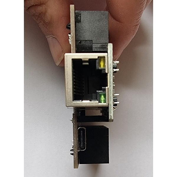
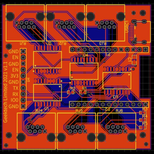
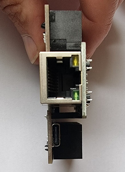
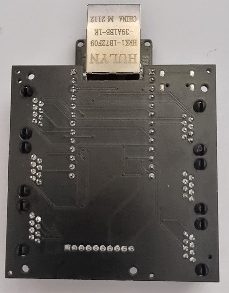
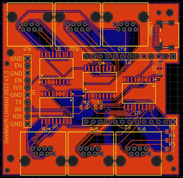
The design is a GPIO Shield for the WT32-ETH01 from wireless tag. The WT32-ETH01's have their pins on the circuit side of the board. You can't insert them into a bread board for prototyping. Inverting the board and using female headers results in a nice and compact package. Allowing a cutout to accommodate the inverted board, to allow for the Ethernet Port, when installed in the shield.
The MCP23008 has programable internal pullup resistors making it suitable for my project.
To allow programing of the ESP32 with the board installed the GPIO0, TX, RX, 3V3 and GND pins are exposed on a header (this is unnecessary as the board can simply be programmed before inserting)
Parts List
| Name | Designator | Quantity | Manufacturer Part | Manufacturer | Supplier | Supplier Part | Price |
| 10uF | C1 | 1 | CL21A106KAYNNNE | SAMSUNG | LCSC | C15850 | 0.012 |
| A2541WV-10P | H1 | 1 | A2541WV-10P | Changjiang Connectors | LCSC | C225485 | 0.161 |
| Header-Female-2.54_1x13 | P1,P2 | 2 | Female header 2.54-1*13P | BOOMELE | LCSC | C52709 | 0.098 |
| 4.7K | R1,R2,R3,R4,R5 | 5 | PTFR0603B4K70P9 | ResistorToday | LCSC | C328429 | 0.052 |
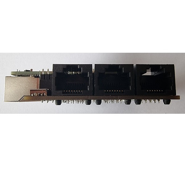
| R-RJ45R08P-A004 | RJ1,RJ2,RJ3,RJ4,RJ5,RJ6 | 6 | R-RJ45R08P-A004 | Shenzhen Cankemeng | LCSC | C385834 | 0.147 |
| MCP23008T-E/SO | U1,U2,U3,U4 | 4 | MCP23008T-E/SO | MICROCHIP | LCSC | C145701 | 2.22 |
| TYPE-C-31-M-12 | USBC1 | 1 | TYPE-C-31-M-12 | Rectangular Connectors - Contacts | LCSC | C165948 | 0.287 |
Cost wise their is a minimum order of 5 PCBs with the option to have the components mounted on a minimum of 2 boards.
Including shipping and surface mounting 2 boards the cost was only $52.89.
Testing the IO Shield
As the intended WT32-ETH01's had not arrived I ended up testing the IO Shield with a NodeMCU, Confirming the the MCP23008's where addressable and working to each of the RJ45's as intended.
Programing the WT32-ETH01
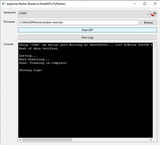
The WT32-EHT01's do not have an on-board serial to TTL chip like the ESP8266/NodeMCU devices do. To program the board with ESPHome, you can use a NodeMCU as a TTL serial connection. To do this you simply connect the EN (Enable) pin to ground. This puts the board into pass-through mode, and connects RX & TX to RX & TX on the WT32-ETH01 plus GND and 3V3, to provide power. To put the WT32-ETH01 into programming mode, connect GPIO0 to Ground. Then use your favorite flashing application to install the firmware.
Final testing picked up a minor issue that 3 of the GPIO pins from the WT32-ETH01 do not have internally programable pull-up resisters. Unfortunately, the manual for the WT32-ETH01 does not mention this, other than that the 3 affected pins can be used for input only. GPIO 35,36 and 39 its a simple enough fix to add external pull-ups if this IOs is required. With 35 windows and doors to monitor, they will all have electronically-monitored locks. This is a non-issue for me.
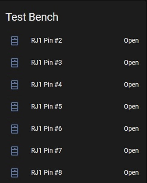
ESPHome Binary Sensor
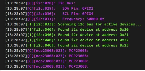
i2c: sda: GPIO2 scl: GPIO4
mcp23008: - id: 'mcp23008_hub0' address: 0x20 - id: 'mcp23008_hub1' address: 0x21 - id: 'mcp23008_hub2' address: 0x22 - id: 'mcp23008_hub3' address: 0x23
binary_sensor: - platform: gpio name: "RJ1 Pin #2" device_class: window pin: mcp23xxx: mcp23008_hub1 number: 0 mode: INPUT_PULLUP inverted: false - platform: gpio name: "RJ1 Pin #3" device_class: window pin: mcp23xxx: mcp23008_hub1 number: 1 mode: INPUT_PULLUP inverted: false
Home Assistant
Updated Design Version 1.1
Updated with external pull-up resisters for the affected GPIO's
Wiring the Windows
To keep things neat and tidy, each string of 7 windows will be terminated into the patch panel. This keeps the wiring under control, and hopefully trouble-shooting to a minimum.
- Magnetic Reed Switches
- 8 Core Security Cable
- T-Tap connectors for Ground Bus connections
- K2 Crimps reed switch connections
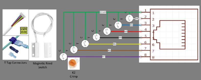
The gel-filled K2 crimps are very reliable and fast to install.
Final Thoughts
Would I order a custom circuit again? Absolutely! After prototyping an idea you end up with a mix of jumper wires, breadboard and sensors. For example, my Raspberry Pi I had running as a weather station, used various sensors and relays to control watering. I dare not go near it, as if one of the jumper wires fell out, it was a nightmare to trouble-shoot. EasyEDA is my new favorite site! It has enabled me to turn some of my long-time prototypes into a more sophisticated and robust circuit. This is high on my list of things to do, when I get the time.