Part 2 – Upgrading the Pulse 2 Hub with an External Whip Antenna
The Pulse 2 Hub is a surprisingly capable little device, let down mostly by its cloud-first firmware design and some questionable RF engineering decisions. In Part 1, I covered flashing ESPHome onto the hub and taking back local control.
This post goes deeper—literally—into the RF side, where a simple hardware mod can dramatically improve range and reliability.
The stock hub uses a tiny printed F-style PCB antenna for 433 MHz. It works… okay… as long as you’re in the same hemisphere as your blinds. Through walls? Behind a fridge? Inside a steel frame house? Forget it. Once I moved control logic off AWS IoT (which was adding ~200 ms of latency by punting everything to us-east-1), the next obvious bottleneck was the RF path.
Good news: the designers actually left a u.FL footprint on the board—completely unpopulated, but ready to go. With a few minutes of soldering, you can bypass the onboard antenna and install a proper 433 MHz whip.
Why Add an External Antenna?
A 433 MHz system lives or dies by antenna quality. The wavelength is long (~69 cm), and PCB antennas this small are pure compromise. An external quarter-wave whip (around 165 mm) radically improves link budget:
-
Up to +10 dB gain line-of-sight
-
3–5× better penetration through walls
-
More consistent two-way ACKs from blind motors
-
Far fewer packet retries
-
Allows full-house coverage from a single hub
This mod turns the Pulse 2 from “barely works” to “rock solid”.
What You’ll Need
-
Fine-tip soldering iron
-
Tweezers + flux
-
u.FL (IPEX) SMD connector
-
u.FL-to-SMA pigtail (female bulkhead)
-
433 MHz external whip antenna
-
Small Phillips screwdriver
-
Optional: hot glue for strain relief
Step 1 – Open the Pulse 2 Hub
Flip the unit over and remove the screws under the rubber feet.
The lid separates cleanly and exposes the main RF/ESP32 board.
Inside, you’ll see:
-
The ESP32 module
-
The STM32 that handles the ARC UART
-
The printed 433 MHz antenna trace along the PCB edge
-
An unpopulated u.FL pad footprint right next to it
This is the jackpot.
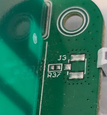
Step 2 – Identify the Antenna Select Pads
Near the u.FL footprint is a tiny passive network that allows the designer to switch between:
-
Internal PCB antenna, or
-
External connector (u.FL)
Currently, an unpopulated R37 (0-ohm) routes the RF path to the F-style PCB antenna.
To route RF out to the u.FL connector:
-
Install the 0-ohm link R37 feeding the onboard antenna
-
Install the u.FL connector
On the Pulse 2 board, it’s a simple disconnect → reconnect workflow.
Step 3 – Remove the F-style Antenna Link
Remove the RF line to the PCB antenna.
-
Add a bit of fresh solder
-
Wick away the solder using desoldering braid
-
Confirm the F antenna is disconnected with a mulitmeter
This isolates the printed antenna so it can’t load or detune your new external whip.
Step 4 – Solder the u.FL Connector
Align the u.FL connector on its footprint.
It’s tiny—use flux and work under good light.
Procedure:
-
Tack one mechanical pad
-
Align perfectly
-
Solder the other two grounding legs
-
Finally solder the RF center pin
A continuity check should show the RF feedline now accessible through the connector.
Step 5 – Add the u.FL → SMA Pigtail
Route the pigtail through the case:
-
Drill a small hole in the rear housing
-
Install the SMA bulkhead
-
Tighten the nut from inside
-
Plug the u.FL end into the board
-
Add strain relief (a dot of hot glue works great)
This keeps the cable from tearing off the tiny connector when you move the hub.
Step 6 – Attach a Proper 433 MHz Whip
Use any standard 433 MHz quarter-wave whip:
-
165 mm length
-
SMA or RP-SMA depending on your pigtail
-
Flexible options work best around curtains/blinds
-
Magnetic bases also work if you want it remotely mounted
Avoid stubby antennas—they’re nearly always electrically too short and perform terribly.
Step 7 – Reassemble & Test
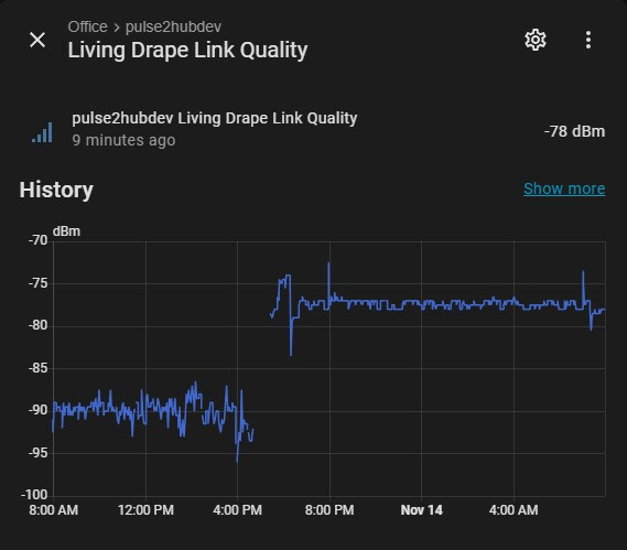
Power the hub back up and watch your logs.
You should see:
-
Fewer retries
-
Lower RSSI variance
-
Faster ACK responses
-
Commands reaching blinds that previously “randomly failed”
In my install, I saw:
-
~10 dB improvement line-of-sight
-
3–4 dB through typical internal walls
-
Full-house coverage with zero dead spots
The difference is night and day.
Final Thoughts
The Pulse 2 Hub hardware is honestly quite decent—especially once you throw ESPHome on it—but its RF output was always the Achilles heel. By enabling the connector the designers clearly intended to include, the hub performs more like a commercial RF gateway than a toy.
This is a simple 15–20 minute mod that costs under $10 in parts and unlocks far better stability, range, and responsiveness.
If you’ve already reflashed your Pulse 2 and want to squeeze every last drop of performance out of it, this is absolutely worth doing.