Installing ESPHome on the Rollease Acmeda Pulse 2 Hub
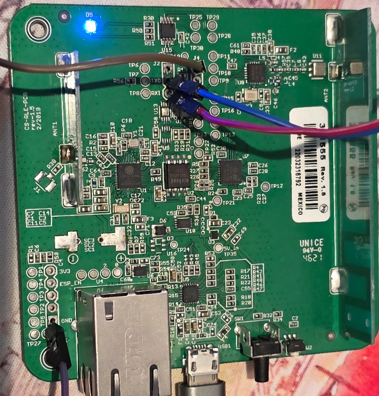
The Rollease Acmeda Pulse 2 Hub can be repurposed into a powerful ESPHome-based ARC bridge by flashing custom firmware directly onto its onboard ESP32-D0WD-V3 module. The hardware is very similar to the WT32-ETH01 with a physical ethernet port.
This allows direct serial communication with ARC-protocol blind motors, removing the need for the original cloud firmware or mobile app.
Hardware Overview
| Component | Function | Notes |
|---|---|---|
| ESP32-D0WD-V3 | Main microcontroller | Dual-core Xtensa chip (Wi-Fi/Bluetooth capable). Runs ESPHome firmware. |
| Winbond 25Q32JV | 32 Mbit SPI Flash | Stores firmware and settings. |
| LAN8720A | Ethernet PHY | Provides wired Ethernet over the RJ45 jack. 50 MHz crystal driven. |
| PCA9554 | I²C I/O Expander | Manages GPIOs for LEDs |
| ATECC508A | Crypto authentication chip | Used by the stock firmware for AWS IoT authentication. |
| STM32L051C6 | Sub-MCU for RF control | Handles 433 MHz radio transceiver and motor pairing logic. |
| Si4462 (EZRadioPRO) | 433 MHz RF Transceiver | Silicon Labs sub-GHz radio connected to the STM32 via SPI; provides ASK/FSK/OOK modulation and RSSI reporting per Si446x datasheet. |
| F-Antenna | Printed 433 MHz antenna | Original PCB-trace F-antenna for better range. |
| UART Transceiver | UART interface | Connects the ESP32 to the STM32 for ARC serial communication. |
ESP32 Pin & Bus Mapping
| Function | GPIO | Connected Device / Notes |
|---|---|---|
| UART TX → STM32 RX | GPIO 15 | ARC serial data (ESP → STM32) |
| UART RX ← STM32 TX | GPIO 13 | ARC serial data (STM32 → ESP) |
| Ethernet MDC | GPIO 16 | LAN8720 management interface |
| Ethernet MDIO | GPIO 23 | LAN8720 management interface |
| Ethernet Clock EXT_IN | GPIO 0 | 50 MHz clock from PHY |
| Ethernet Power Enable | GPIO 2 | Powers the LAN8720 |
| I²C SDA | GPIO 14 | PCA9554 / ATECC508A bus |
| I²C SCL | GPIO 4 | PCA9554 / ATECC508A bus |
| Button 1 (Pair) | GPIO 36 | Triggers send_pair_command() |
| Button 2 (Reboot) | GPIO 39 | Calls ESP.restart() |
| 3 × LEDs (Red/Blue/Green) | PCA9554 #0–#2 | Controlled via I²C expander |
| Optional STM32 Enable | PCA9554 #4 | Disabled by default (can be re-enabled if needed) |
Electrical Architecture
-
The ESP32 communicates with the STM32L051 over UART (115200 baud, 8N1).
-
The STM32 controls the RF transmitter for ARC radio communication.
-
The LAN8720A provides wired Ethernet; clocked externally through GPIO 0.
-
The PCA9554 handles LED outputs and expansion pins via I²C (SDA = GPIO 14, SCL = GPIO 4).
-
Power distribution is 3.3 V throughout the logic section.
This architecture allows ESPHome to use Ethernet networking while simultaneously driving the RF microcontroller through UART.
Programming & Debug Interface
The Pulse 2 Hub is based on an ESP32-D0WD-V3 module, which exposes a standard UART bootloader interface suitable for programming via USB-to-serial adapters such as FTDI Basic, CP2102, or CH340. The RX and TX pins for the ESP are clearly labeled, also the RX and TX pins for the STM32L051C6 are also exposed but likely the flash protection for the RF firmware will be enabled to prevent extraction.
UART Boot Pins
| Signal | ESP32 Pin | Function | Notes |
|---|---|---|---|
| TX (ESP32 TX0) | GPIO 1 | Transmit from ESP32 → to USB-Serial RX | Used for flashing and serial logs |
| RX (ESP32 RX0) | GPIO 3 | Receive to ESP32 ← from USB-Serial TX | Connect to host TX line |
| GND | GND | Common ground | Must be shared with USB-Serial adapter |
| EN | EN (RESET) | Reset / power enable | Pull LOW → reset ESP32 |
| BOOT | GPIO 0 | Bootloader select | Hold LOW during reset to enter flashing mode |
Note: GPIO 0 is located behind the ethernet shield, it is the far right pad labeled '0'
These are the same pins used by the onboard firmware for serial flashing. Once programmed, ESPHome disables UART0 logs to free TX/RX for other functions.
Boot & Flash Procedure
-
Connect a 3.3 V USB-to-Serial adapter:
-
Adapter TX → ESP32 RX (GPIO 3)
-
Adapter RX → ESP32 TX (GPIO 1)
-
Adapter GND → Board GND
-
-
Pull GPIO 0 → GND (BOOT mode).
-
Momentarily pull EN → GND to reset.
-
Flash ESPHome via
esphome run pulse2hub.yaml --device /dev/ttyUSB0. -
Release GPIO 0 to return to normal run mode.
ESPHome Highlights
-
Ethernet: Fully functional via LAN8720 (GPIO 16/23/0/2, phy_addr 1)
-
I²C: PCA9554 expander controls RGB LEDs
-
UART: Bridges to STM32 for ARC protocol
-
Buttons:
-
GPIO 36 → Pairing (
!000&;) -
GPIO 39 → Software reboot (
ESP.restart())
-
-
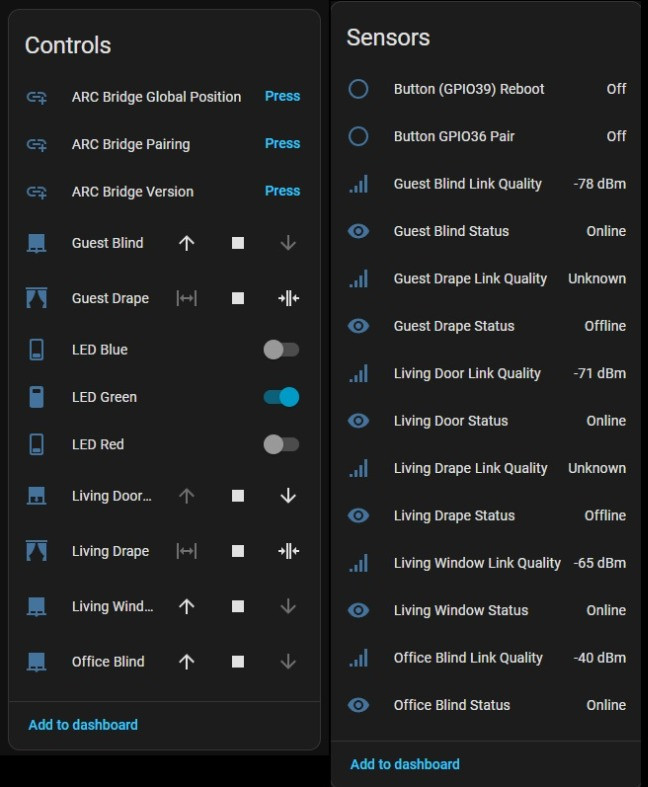
Covers: Six motorized blinds defined via the
arc_bridgecomponent -
Sensors: Each blind exposes
Link Quality (dBm)andStatus (Online/Offline/Not paired)
YAML Configuration Summary
esphome:
name: pulse2hubdev
friendly_name: pulse2hubdev
on_boot:
priority: -200
then:
- logger.log: "Waiting for Ethernet link ..."
- wait_until:
lambda: 'return id(eth0).is_connected();'
- logger.log: "Ethernet up"
- switch.turn_on: green
esp32:
board: esp32dev
framework:
type: arduino
version: recommended
logger:
level: DEBUG
baud_rate: 0 # disable serial logging, free UART0 pins
ethernet:
id: eth0
type: LAN8720
mdc_pin: GPIO16
mdio_pin: GPIO23
clk:
pin: GPIO0
mode: CLK_EXT_IN
phy_addr: 1
power_pin: GPIO2
web_server:
port: 80
i2c:
id: i2c_bus
sda: GPIO14
scl: GPIO4
frequency: 100kHz
scan: false
pca9554:
- id: pca9554a_device
i2c_id: i2c_bus
address: 0x41
switch:
- platform: gpio
name: "LED Red"
id: red
pin:
pca9554: pca9554a_device
number: 0
mode: { output: true }
inverted: true
- platform: gpio
name: "LED Blue"
id: blue
pin:
pca9554: pca9554a_device
number: 1
mode: { output: true }
inverted: true
- platform: gpio
name: "LED Green"
id: green
pin:
pca9554: pca9554a_device
number: 2
mode: { output: true }
inverted: true
button:
- platform: template
name: "ARC Bridge Pairing"
icon: "mdi:link-plus"
on_press:
- lambda: |-
id(arc)->send_pair_command();
- platform: template
name: "ARC Bridge Version"
icon: "mdi:link-plus"
on_press:
- lambda: |-
id(arc)->send_simple("000", 'v', "?");
- platform: template
name: "ARC Bridge Global Position"
icon: "mdi:link-plus"
on_press:
- lambda: |-
id(arc)->send_simple("000", 'r', "?");
binary_sensor:
- platform: gpio
name: "Button GPIO36 Pair"
pin:
number: GPIO36
mode:
input: true
inverted: true
on_press:
- lambda: |-
id(arc)->send_pair_command();
- platform: gpio
name: "Button (GPIO39) Reboot"
pin:
number: GPIO39
mode:
input: true
inverted: true # flip to true if the logic is active-low
on_press:
then:
- lambda: |-
ESP_LOGI("reboot", "Manual reboot triggered via GPIO39");
ESP.restart();
external_components:
- source: github://redstorm1/arc-bridge
components: [arc_bridge]
refresh: 1s # optional while iterating to force refetch
uart:
- id: rf_a
rx_pin: GPIO13 # STM32 RX ← ESP TX
tx_pin: GPIO15 # STM32 TX → ESP RX
baud_rate: 115200
data_bits: 8
parity: NONE
stop_bits: 1
rx_buffer_size: 4096
arc_bridge:
id: arc
uart_id: rf_a
cover:
- platform: arc_bridge
bridge_id: arc
id: usz
device_class: shade
name: "Office Blind"
blind_id: "USZ"
link_quality: lq_usz
status: status_usz
sensor:
- platform: template
id: lq_usz
name: "Office Blind Link Quality"
unit_of_measurement: "dBm"
icon: "mdi:signal"
text_sensor:
- platform: template
id: status_usz
name: "Office Blind Status"
Functional Summary
Once flashed with this configuration, the Pulse 2 Hub behaves as a standalone ARC bridge:
-
Periodically queries each blind for position and RSSI.
-
Automatically updates Home Assistant entities (
Online,Offline,Not paired). -
Provides a pairing button (both virtual and physical).
-
Fully controllable covers — open, close, stop, move to %, or tilt.
-
Ethernet connectivity provides a robust, low-latency link.
-
Local-only operation — no OEM firmware or cloud required.
Result
With ESPHome running, the Pulse 2 Hub becomes a self-contained, LAN-connected ARC gateway.
It retains all original hardware functionality — Ethernet, RGB LEDs, pairing button, and RF radio — but now integrates natively with Home Assistant for complete, privacy-friendly blind automation.
ESP Web Interface

Home Assistant Entities
External Whip Antenna Upgrade
In the next stage, I’ll be adding an external 433 MHz whip antenna to improve RF range and reliability.
The Pulse 2 Hub PCB conveniently includes an antenna pad and link selector near the RF section — a 0 Ω link or solder jumper that routes the RF feed between the on-board printed F-antenna and the external antenna pad.
By removing the link to the PCB trace and soldering a short coax (e.g. RG-174 or U.FL pigtail) to the pad, the signal can be routed to an external whip or SMA bulkhead connector mounted on the enclosure.
This modification isolates the internal antenna and allows for:
-
Higher-gain omnidirectional or whip antennas
-
Flexible placement for better reception across multiple blinds
-
Reduced interference from the chassis and Ethernet shielding