Improving Range on Versa / Dooya / Tuya Drape Motors
Adding an External 433MHz Antenna (and Gaining ~11 dB Link Quality)
Most low-cost curtain/drape motors (Versa, Dooya, Tuya-based units, etc.) ship with a printed PCB antenna inside the motor housing. It works, but it’s trapped against the motor body, wiring bundle, and plastic enclosure – so RF performance is marginal at best. In my case, it resulted in weak signals and intermittent control from the other side of the house.
This write-up covers how I added an external antenna safely via the RF feed point. The modification resulted in a measured ~10–11 dB link improvement (from ~-84 dBm to ~-73.5 dBm), which translates to a substantial boost in usable range and reliability.
Before & After: Link Quality Change
| Condition | RSSI (approx.) |
|---|---|
| Stock setup | -84 to -86 dBm (borderline) |
| After antenna mod | -73.5 dBm (stable / reliable) |
Graph excerpt:
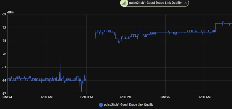
This is not placebo. 10+ dB is roughly the difference between “barely works” and “works reliably through walls”.
The Hardware
-
Versa / Dooya motor drive unit (433 MHz)
-
Internal PCB antenna
-
Exposed RF feed point on the logic board
-
Matching network before PCB trace
Example of board layout:
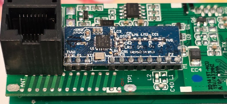
The antenna trace is the long green meander marked ANT. The point we care about is TP1 (Test Point 1), directly after the RF matching network.
Identifying the Correct Connection Points
The important thing is to feed the new antenna at the RF feed point, not at the antenna itself, and not at random 3V3/GND points. At DC the feed point may appear tied to power/ground due to the choke and matching network – that’s normal.
Connection Summary
| Wire | Location | Why |
|---|---|---|
| Center conductor | TP1 | Direct RF feed before PCB antenna |
| Shield/braid | Ground stitching vias beside TP1 | Low-inductance RF ground reference |
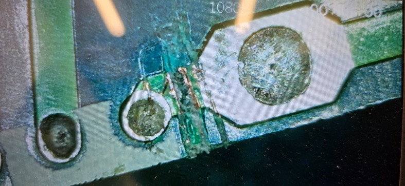
I confirmed this on the board before modification:
RF IC → matching network → TP1 → PCB antenna
Isolating the feed here avoids detuning the original antenna. And is reversable if required.
Step-by-Step Modification
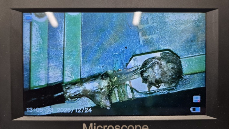
1. Open Housing & Access the PCB
Remove the cover and expose the logic board. The PCB antenna will be located near the top edge.
2. Isolate the Original Antenna
Cut the ANT trace after the feed point. This prevents the internal antenna from loading the new one.
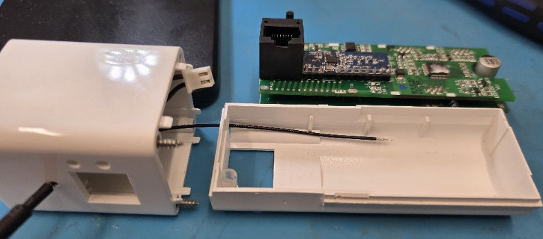
3. Install Coax Feed
- Route the Antenna via the openings available no mods required
-
Center core → TP1
-
Shield → via-to-ground next to TP1
-
Keep lengths short and neat
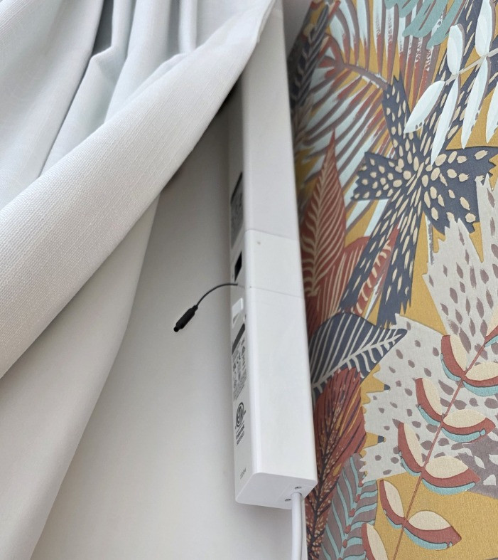
4. Reassemble & Route the Antenna Outward
I exited the wire through a side seam and let the antenna sit clear of the housing.
This alone gave the 11 dB improvement.
Why External Placement Helps
Inside the housing the antenna is surrounded by:
-
Motor windings (metal mass)
-
Control cabling
-
PCB ground plane
-
Plastic enclosure
Relocating the radiator to the outside removes those detuning factors and allows a cleaner radiation pattern.
As its hidden by the drape it is invisible while still performing much better.
Final Result
This isn’t a “hacky wire hanging off a board”; it’s using the correct RF feed point, proper ground reference, and tuned radiator length. The end result is a drape motor that behaves like a product with a proper antenna design – which it should have had from the factory.
If you follow the steps above, expect 8–12 dB improvement depending on environment and placement. For me, this changed the motor from barely responding to instantly responding anywhere in the house.
Parts Used
External Antenna
433 MHz External Whip Antenna – RG1.13 Coax (Welded Type)
-
Size: ~23 mm base, 3 dBi rated
-
Cable: RG1.13 coax with tinned end (no connector required)
-
Frequency options listed: 433/470/868/915 MHz (use the 433 MHz model)
-
Purchased as a 2-pack, approx. NZD $3.36/lot
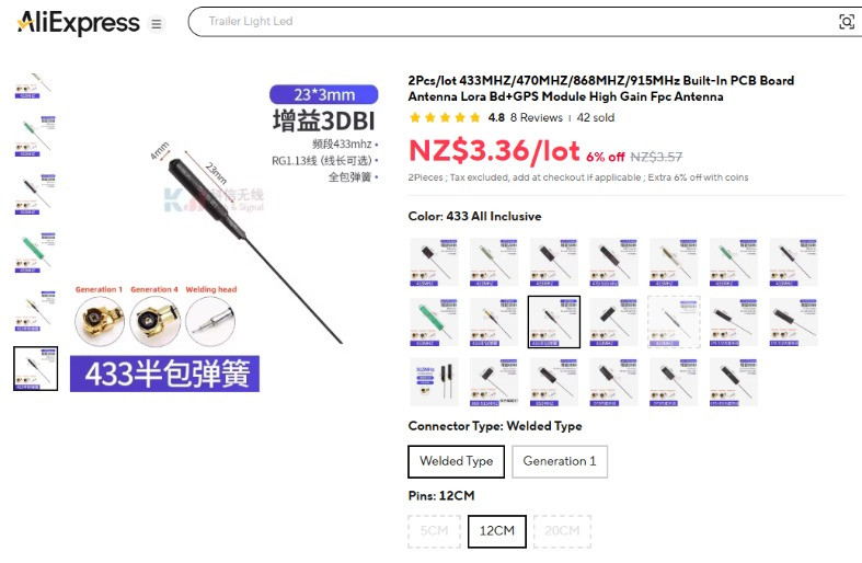
This is the unit I used for the mod. The welded/tinned version is ideal because it solders directly to TP1 (signal) and the RF ground vias without needing an SMA or u.FL connector.
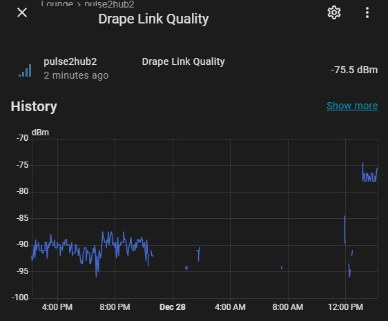
Follow-Up: Final Motor Fixed with Antenna Mod
The last device that was still giving me trouble has now been modded as well, and the results speak for themselves. This motor was barely usable before — constantly dropping off the bus and failing to respond to ARC commands due to a weak ~-90 dBm signal. After applying the same antenna ground fix and adding a proper external radiator, the link quality jumped to around -76 dBm, an improvement of roughly 14 dB.
For context:
A 14 dB increase is the RF equivalent of making the radio link more than 20× stronger from the receiver’s perspective. The difference is immediate — where it previously struggled to connect, it’s now rock-solid and responds first time, every time.
What started as a motor that “barely connected” is now in the reliable / production-grade range. With this last upgrade done, every motor onsite is now stable, responsive, and holding consistent signal levels again.